What is the role of Slicing in 3D printing?
Feb 18, 2022

Humans are gifted with senses that help make decisions and perform activities. Like humans, machines have methods of processing information. Machines also use tools at their disposal to translate a set of instructions into formidable actions. That is how all machines work and 3D printing is no different.
“3D printing, also called additive manufacturing, turns digital files into physical objects by building them up layer-by-layer. Imagine a cucumber sliced into paper-thin slivers by a mandolin and then put back together.”
Whenever we talk about 3D printing, we hear certain terms repetitively. “Slicing” is one such word that can not be ignored. It is the intermediate and most important step in the process of 3D printing. In this article, we will try to understand the role slicing plays in 3D printing.
Here is a list of sub-topics that will be part of this discourse :
- What is Slicing?
- Components of a Slicing Software
- Features of a Slicing Software
- FDM vs SLA Slicer
- The ultimate list of Slicer Softwares
1. What is Slicing?
The act of converting a 3D model into a set of instructions for the 3D printers is called Slicing. Quite literally, it ‘slices’ the 3D model into thin layers, and further determine how each layer should be printed (the tool path) to get minimum time, best strength, etc.
A slicer software takes a 3D CAD model which is generally an STL format file and converts it into a g-code that gives commands to the printer. Following are the three major types of settings that can be controlled in a slicer software —
- Print Settings: layer heights, shells, infill per cent, and speed
- Filament Settings: filament diameter, extrusion multiplier, the temperature of the extruder, and print bed.
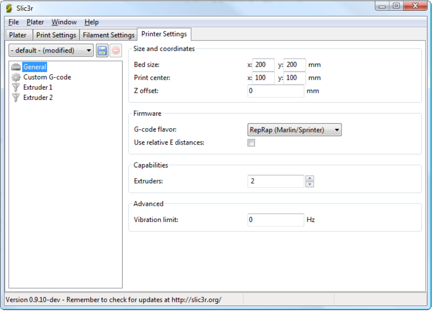
- Printer settings: nozzle diameter, print bed shape (L x W), and Z offset.
In the next few sections, we will delve into some of these Slicer settings that will directly impact the 3D print quality of the models.
2. Components of a Slicing Software
It is important to understand how data flows in the 3D printing process.
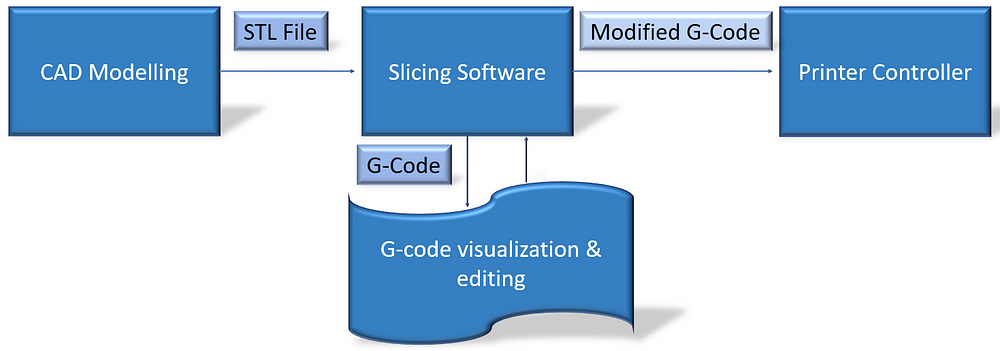
Like every software, we can divide it into two components — front-end & backend, OR — GUI and Logic. The front-end consists of the parts that the user directly interacts with. This is where the user visualizes the CAD, as well as the gCode and tool path. The back-end components contain algorithms or instructions for the code execution. Let us look at the components of the Slicer software.
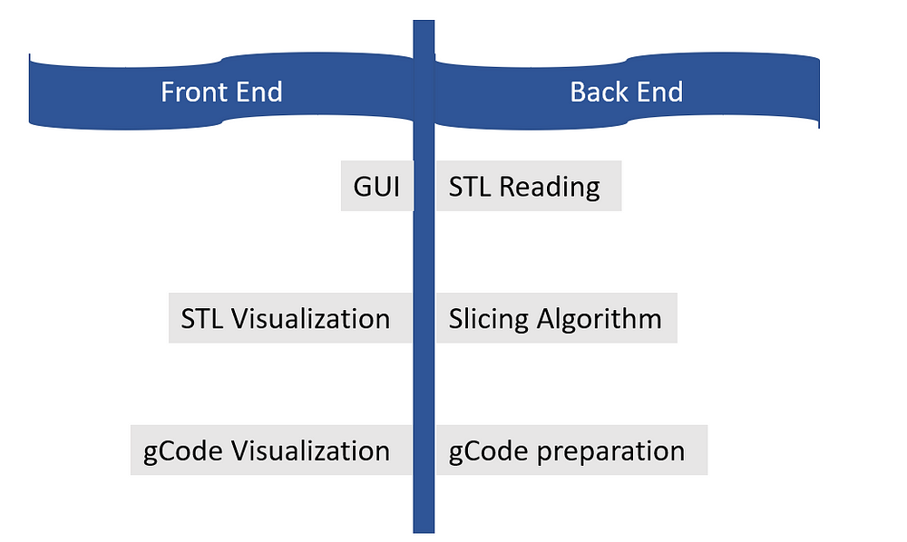
Front End
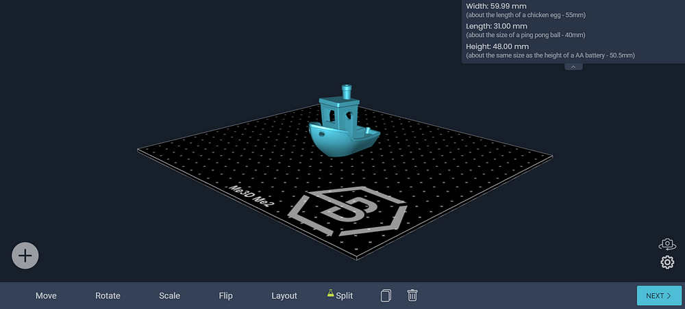
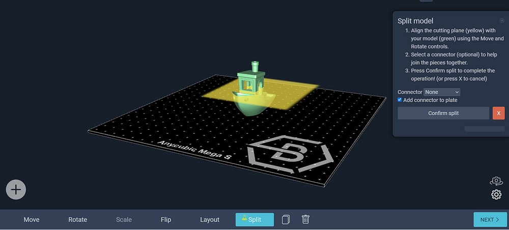
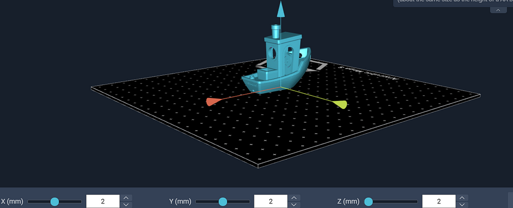
GUI is the graphic user interface. It has all the tools that help the user interact with the 3D model. As you can see in the picture below, the graphic user interface of a free web-based software named Buildbee. It enables the user to move, scale, rotate, and change the settings for the 3D model.
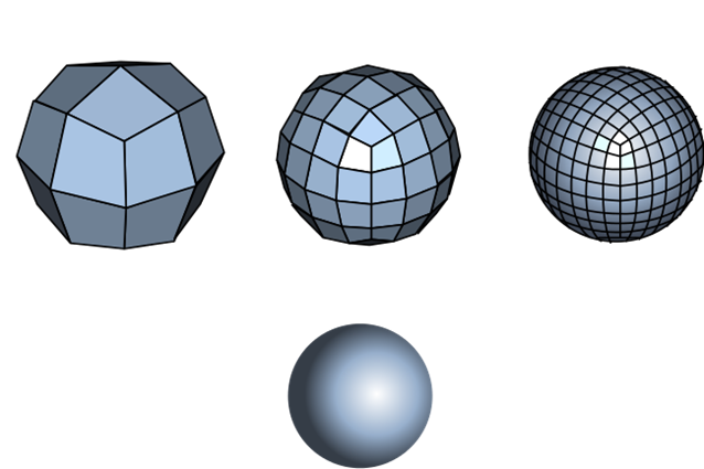
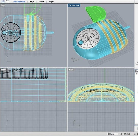
The main function of the slicing software is to work with the STL format file. It stores the visual image of the 3D model. It stands for “STeroLithography,” sometimes also called — Standard Triangle Language/Standard Tessellation Language. It has information regarding the surface geometry of the model. In a nutshell, it encodes the model description for the slicer to pick up and display the visuals. The word “tessellation” is associated with STL files as it breaks down the complex 3D structures into 2D models. In the image below, we see that a sphere can be represented using a bunch of small squares or triangles.
Certain tessellation rules help in giving a good 3D print quality.
- Vertex to vertex rule: every triangle must share 2 vertices of its adjacent triangle.
- Orientation rule: The direction of the normal vector has to point outwards and the vertices are listed in anti-clockwise order while viewing the object.
- All positive octant rule: The coordinates of the model must be all positive.
Things to keep in mind while exporting the STL —
- Angle control: Gaps between the triangles prevent angle deviation and improve print resolution.
- Chordal deviation: A parameter called the chord height (maximum distance between the surface of the design and the STL diagram) needs to be maintained. The chord tolerance is set between 0.01 to 0.001 mm as a standard.
- Binary/ASCII: STL files can be shared in two types of encoding; Binary & ASCII. Binary files are small and ASCII files are large in size.
Back End — The logic
The back-end handles —
- Reading the STL
- Slicing STL into layers and determine the tool path to print the object, and
- Writing the gCode
The most important component of the slicing process is the gcode. Based on the user inputs, the back-end generates an optimized code to print the object. A gcode is nothing but the set of commands to execute the print action. It helps in providing instructions to the machine controller. A 3D slicer generates this gcode automatically.
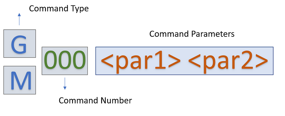
A deeper understanding of the gcode can help one troubleshoot issues while 3D printing. There are two types of commands — “G” & “M” here is the basic syntax of the code:
Slicing Algorithm: Understanding the G-code
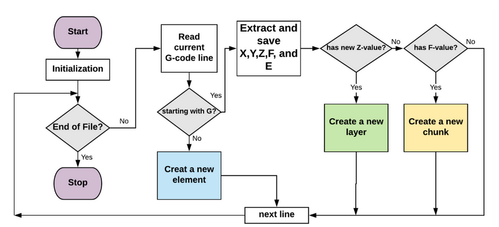
We can convert the facets (from the stl file) into separate segments through a slicing algorithm. The algorithm looks at the gcode and extracts the information accordingly. It helps in understanding the gcode to help slice the model into smaller parts.
So far we have looked at the components that enable the slicing of a CAD output model. It’s now time to look further into some more features that will help us print the best quality 3D objects.
3. Features of a Slicing Software
Once you retrieve the STL file from the CAD software, there are certain settings in the software that you must cater to…
Orientation
After loading the stl file on the slicing software, we need to align the 3D model to the given space. As mentioned above, one has to follow the orientation rule.
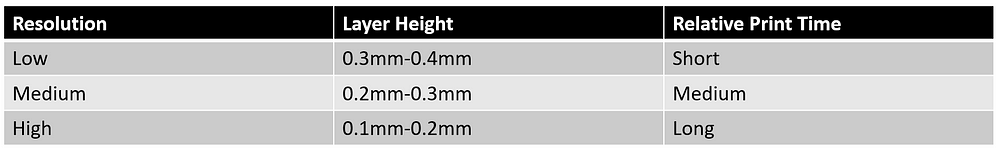
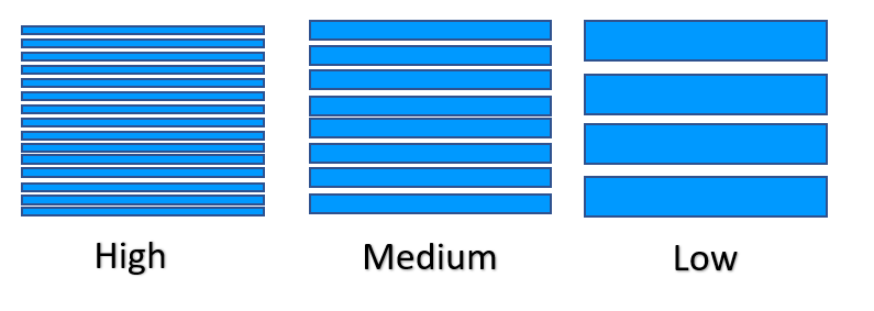
Layer Height (Object resolution)
The resolution of a 3D object is highly dependent on its layer height. Smaller layer heights give high resolution and smooth surface. However, the overall printing time could be more.
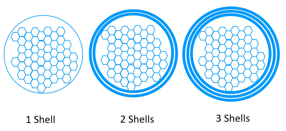
Object Shells (Shell Thickness)
The outer layer that builds the wall of the object is called the object shell or perimeter. The strength of the object is dependent on the number of shells present. Higher shell count → higher strength!
Infill
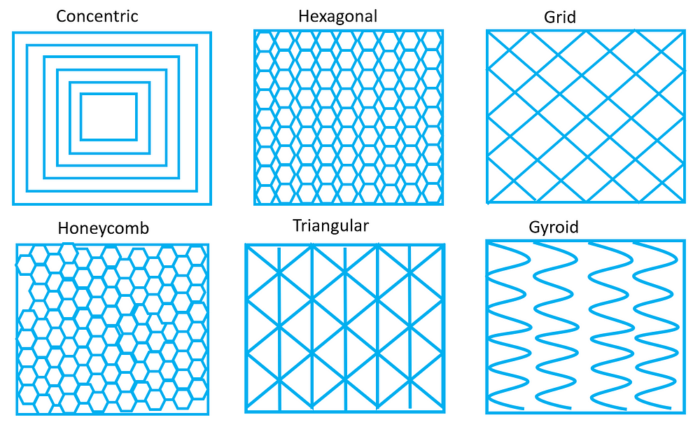
Density: Infill density is measured in % percentage. It can range from 0–100%. An object with 0% will have a hollow interior and an object with 100% density will be solid. Objects with high density will have a longer printing time. The recommended shape for the infill for optimal speed and strength is a honeycomb structure.
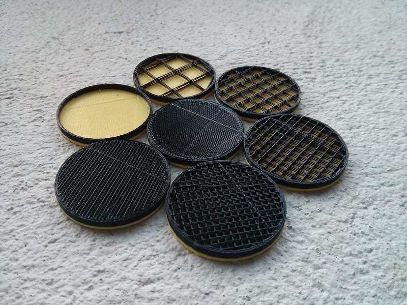
Types/Shapes: The design of the infill pattern can have an impact on the strength and flexibility of the 3D prints. Based on your requirements you can pick the infill type. For eg.,
- Functional prints: Cubic, octet, gyroid
- Figurine and model prints: Lines
- Standard prints: Grid or triangles
- Flexible prints: Concentric
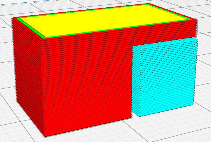
Support Structures
In the processes of 3D printing, one layer is printed over another existing layer. This means every layer needs an underlying layer to support it. If a model has an overhanging part, it still needs a supporting layer. This supporting layer is called the support structure. Slicer software has the ability to insert supports as in where it is needed. The support structures are easily detachable post-printing. In the picture below, the blue color component is the support structure for the given 3D model.
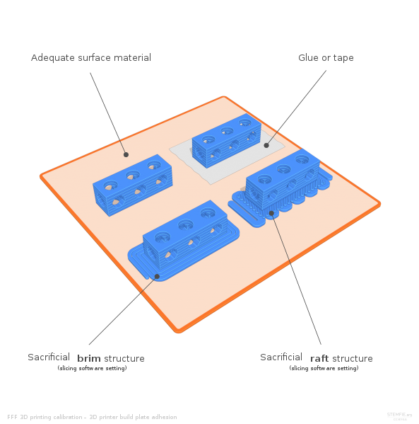
Rafts, skirts, and brims
It is common for 3D printed objects to get stuck on their print beds (physically, not in software). To avoid this, the slicer offers some good solutions. It uses some structures that make the detachment easier.
- Skirt (as shown in fig ‘a’): It is a single outline surrounding the part without touching the actual 3D object.
- Brim (as shown in fig ‘b’): It is a layer printed along the print bed that touches the actual 3D object.
- Raft (as shown in fig ‘c’): A series of layers are printed before the model is printed. It serves as a detachable base for the 3D object.
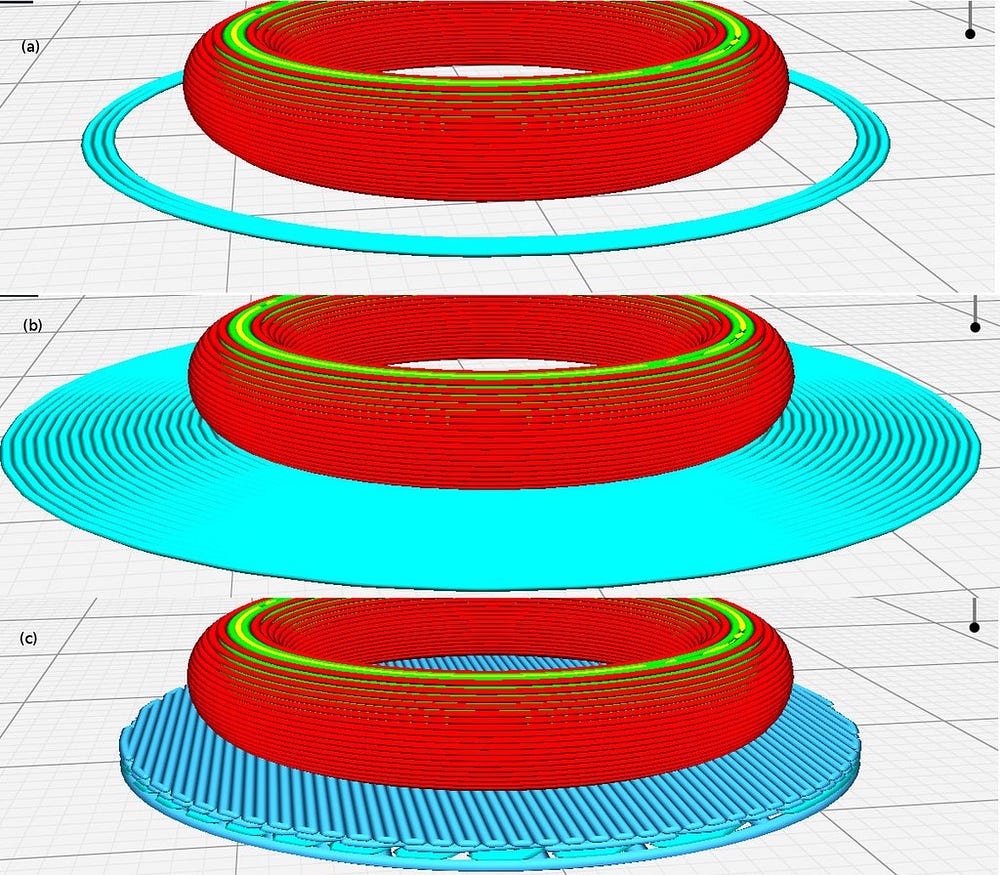
Slicing software gives us these simple techniques to avoid any adhesion to the print bed, which is a common problem in 3D printing.
Print speed
The slicer software has speed settings that can be adjusted based on the geometry of your 3D model. The slicer has default settings for the speed which may be lower than what you might want. The speed can also vary depending on the type of materials you use. Typically, for PLA or ABS the recommended print speed is 40–60 mm/s. Below are the print speed parameters that need to be considered based on the shape of your model.
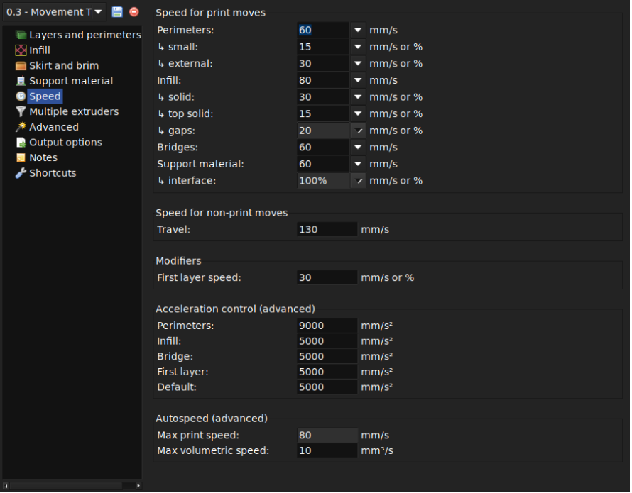
The print speeds are categorized into two types — print moves & non-print moves. Below is a chart to help you understand the different types of print speeds. The travel speed under non-print moves refers to the speed at which the extruder moves from the end of one extrusion to the next. This is crucial in preventing oozing.

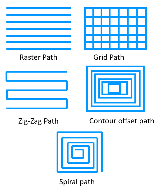
Optimized Print Paths
An optimized printing path is crucial to 3D printing. It affects printing time, surface roughness, strength, etc. Printing paths have a direct impact on the time taken to complete a certain print. A path planning strategy can help optimize the overall printing process. This will result in a shorter fabrication time. Slicer software has pre-defined print paths that one can select from. Some of the widely used paths are available in slicer softwares such as Cura, Slic3r.
Temperature
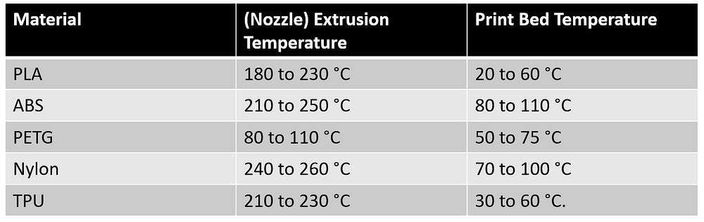
One of the most important slicer settings is the temperature. It needs to be calibrated as per the print speed settings. It is important to increase the temperature if the print speed is set to a higher number. This is because, if the print speed is not matched to the temperature, it can lead to “under extrusion” due to improper melting of filaments. Also, high temperatures can lead to “over extrusion” and result in blobs or zits. It is recommended to increase the temperature between 5–10 degrees Celcius for every 5–10 mm/s rise in the print speed.
Another important factor to consider while controlling the temperature is the type of material used in the printing process. Below is a list of materials with set values of temperatures used in 3D printing.
Dealing with multiple extruders in 3D printing
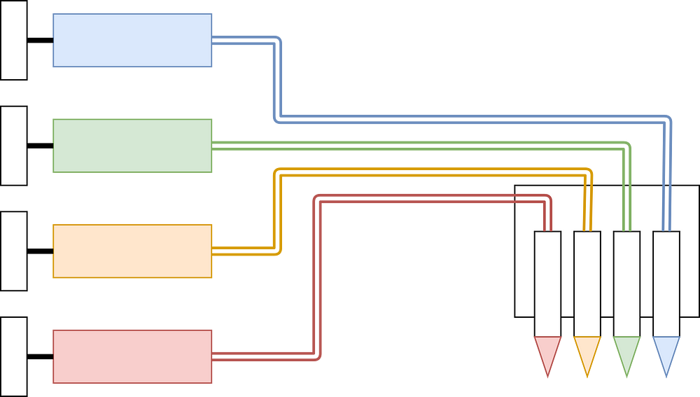
Recently, multi-extruder 3D printers have become popular. Multi-nozzle (or multi-extruder) printers have 2 or more extruders. It is commonly used to print a 3D object with different materials. This type of design can also help reduce the waste generated in the typical single-extrusion method. The printer will have a dedicated nozzle for a given material. It is possible to dedicate one extruder to a certain region and another to a different region. The calibration of the nozzles is important in this case to avoid any mistakes. Using slicing software, it is now easy to assign different roles to each extruder.
Creative Tools Licensed under CC BY-2.0)
Now that we have looked at different parameters for slicer settings, we can look at how these settings may vary for different types of printers.
FDM vs SLA Slicing
FDM and SLA are the two most common techniques in 3D printing. We have often compared these for various characteristics. Let’s look at how the slicing methods differ for each one of these
Before you read any further, don’t forget to check out our detailed coverage of FDM vs SLA printing techniques.
FDM Slicing
The print movement of the extruder or nozzle in an FDM printer is confined to the X and Y axes, while it moves in Z for changing layers. The FDM printers are dependent on the multi-axis control. This needs to be looked after to get the best printing accuracy. Temperature control settings — for heating and cooling of extruders and print beds are important for FDM printers. Some of the best slicer softwares for FDM printers, that have tested pre-defined algorithms to execute the gcode are Cura (free) and Simplify3D (paid).
SLA Slicing
In SLA printing, the build platform moves up and down to dip into the resin tank and form layers one after the other. Therefore, the movement is along the z-axis for SLA printing. The major difference between FDM slicing and SLA slicing is that the SLA printers do not use a gCode as the output file. SLA printers have their own built-in slicing softwares. As SLA printers are devoid of extruders, the nozzle temperatures are irrelevant here. Instead, it has exposure time and lifting speeds as some of the key parameters. There are a few third-party softwares common to SLA printers— ChiTuBox and FormWare.
The Ultimate List of Slicer Softwares
— As of July 2021
- Cura (Basic — Free, Enterprise level — Paid): Latest version is Cura 4.10. The first public version 3.0 was released in September 2017 by Ultimaker. It was developed by David Braam in 2014.
- 3DPrinterOS (Paid): Latest version is 7.3.26 beta (with 2+ weeks of testing). According to their websites, the initial stable version 6.2.3 (with 1000 hours of testing) was launched in February 2020.
- IdeaMaker (Free): Latest version is 4.1.1 release in April 2021. The first public version 2.6.0 was released in May 2017.
- KISSlicer (Basic — Free, Pro — Paid): Latest version is v2 alpha 2.0.6 in May 2020. The first public version KISSlicer 1.6 was released in September 2017.
- Repetier-Host (Free): Latest version is 2.2.2, released in April 2021. The first public version 0.20 was released in September 2011.
- OctoPrint (Free): Latest version is 1.5.3, released in January 2021. The first release was in 2012.
- Slic3r (Free): Latest version is 1.3.0 release in May 2018. Its first public release was in 2011
- AstroPrint (Basic version — Free, Premium version — Paid): The company has set up its cloud-based platform in 2013.
- Simplify3D (Paid): The latest version of Simplify3D is 4.4. Its first public release was in 2013
- IceSL (Free): The latest is IceSL version 2.4.0-beta released in June 2021. The company released its first public version in June 2016.
- Mention our own?
Conclusion
This discussion on slicing software is important with regards to the 3D printing process. The slicing process is crucial in determining the print quality of your 3D models. Therefore, understanding various aspects of slicing can help you manoeuvre the 3D printing process with ease.
3D model slicing is the puzzle piece that completes the 3D printing process. Its role in 3D printing is definitive of the printing standards that you set for your 3D models. We tried to give you a walkthrough of the fundamentals of slicing software that can help you put some obvious doubts to rest.
Despite all the knowledge on slicing settings, 3D prints can still find you in a sticky situation. For those specific times, you can check out our article on fixing 3D print problems!
Don’t forget to share your thoughts or experiences with 3D slicing softwares in the comments below…